

A weld that fails a bend test usually failed before the arc started. Squareness, bevel angle and root face are decided by the cutting tool, not by the welder, and no amount of arc control recovers a joint that was prepared badly.
Fabricators spend most of their capital on the welding side of a joint and most of their scrap on the preparation side. That asymmetry is worth spelling out, because it explains why a 40 kg cutting tool can matter more to first-pass yield than a controller with four hundred stored programs.
Every weld-ready end carries three geometric facts. Squareness is the deviation of the end face from a plane perpendicular to the pipe axis. Bevel angle is the opening that the filler and the arc have to fill. Root face, or land, is the flat strip left at the bore that keeps the arc from dropping through before the root closes. These three numbers, plus root gap, define the volume of metal the welder has to place and the access the torch has to reach it.
Small errors scale badly on large pipe. An end face that is one degree off perpendicular displaces the bevel root by roughly 2 mm on a 114 mm pipe, which is wider than the root gap on most orbital procedures. A five millimetre wall cut with a 1.5 mm land will show a land that varies by plus or minus 0.4 mm across the circumference if the tool is not rigid and centred, and that variation alone is enough to move a joint from full penetration to incomplete fusion on one side while burning through on the other. Nothing in the weld schedule fixes either condition after the fact.
So the practical question when buying preparation equipment is not how fast it cuts. It is how repeatably it produces the same three numbers on joint 1 and joint 400.
Pipe end preparation is usually sold as one category and bought as three, because the machines solve different problems and are rarely interchangeable.
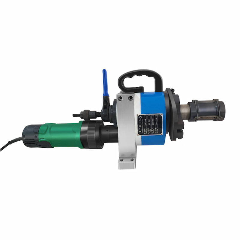
A planetary cutter rotates the cutting tool around a stationary pipe. The pipe does not turn, which means the machine can be clamped onto a long length, onto a spool that is already tacked into a rack, or onto a line that cannot be rotated at all. This is the family that handles field work, and it is the one that decides whether a site tie-in gets a machined end or an abrasive one.
Facing is not cutting through the wall; it is milling the end face flat and square. The distinction matters most on tube sheets, where hundreds of tube ends protrude from a plate and each one has to sit in the same plane so that an orbital head can find it. A facing tool removes the saw burr, corrects the slight out-of-square left by the tube cutter, and establishes a clean datum for the arc.
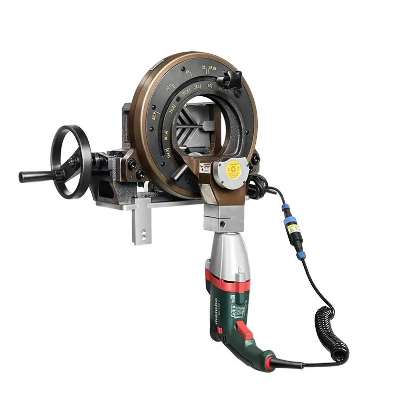
Beveling creates the weld preparation itself: a V, a single-bevel, a U or a compound profile, depending on wall thickness and the code being worked to. Portable electric bevelers are used where the joint geometry has to be produced on site, while stationary machines are used where the same profile is repeated thousands of times in a shop.
Each of these is covered further below with the actual working envelope, because the numbers are what tell you whether a machine fits your pipe range or only appears to.
Cold cutting removes metal by chip formation rather than by melting or abrasion. Three consequences follow directly, and all three are the reason the method is specified on stainless, on duplex, on titanium and on any line where the bore has to stay clean.
The two current models in the range split the small and medium bore work between them. Q3 covers 6 to 76.2 mm outside diameter, Q4 covers 12.7 to 114.3 mm, and both run the same 1,300 W motor at 220 V, 50 Hz with a spindle range of 30 to 160 rpm that steps down automatically as diameter rises.
| Parameter | Unit | Q3 | Q4 |
|---|---|---|---|
| Cutting range, OD | mm | 6 - 76.2 | 12.7 - 114.3 |
| Cutting range, OD | inch | 0.25 - 3.0 | 0.5 - 4.5 |
| Wall thickness, minimum | mm | 1 | 1 |
| Wall thickness, maximum | mm | 5 | 7 |
| Motor power | W | 1,300 | 1,300 |
| Supply | - | 220 V, 50 Hz | 220 V, 50 Hz |
| Spindle speed | rpm | 30 - 160 | 30 - 160 |
| Dimensions | mm | 600 x 420 x 540 | 640 x 465 x 540 |
| Net weight | kg | 38.5 | 50 |
| Gross weight | kg | 55 | 65 |
Two design details do most of the daily work. A quick-change diameter mechanism lets the head be reset across the range in seconds instead of requiring a tooling swap, and a self-centring chuck holds concentricity to within roughly 0.1 mm so the groove geometry stays constant around the circumference. Without the second point the first is only a convenience.
The wall thickness ceiling is not arbitrary. Cutting force rises with chip cross-section, and past about 5 mm in carbon steel on the Q3 frame the spindle and the clamp start to deflect more than the tolerance allows, which is why the heavier Q4 frame takes 7 mm. Pushing a machine past its published wall is the single most common way to produce an end that measures well with a square and still welds badly.
Heat exchanger and boiler work has a different bottleneck from pipeline work. The joint is short, the wall is thin and the count is enormous: a single exchanger can present several thousand tube ends that all have to be faced, cleaned and welded inside a fixed shutdown window. At that scale a hand tool that takes ninety seconds per end becomes the critical path.
Facing solves three problems at once on a tube sheet. It removes the burr left by the tube cutter, which would otherwise sit directly under the arc and create a gas pocket. It establishes an end face square to the tube axis so that the weld head does not have to compensate for a sloped start. And it removes the work-hardened rim that a tube cutter leaves on stainless, which is where lack-of-fusion defects tend to initiate.
| Model | Cutting range, mm | Cutting range, inch | Wall, mm | Net weight, AC |
|---|---|---|---|---|
| XD-1.0 | up to 25.4 | 0.118 - 1.0 | 0.5 - 3.0 | 4.75 kg |
| XD-1.5 | 3.0 - 38.1 | 0.118 - 1.5 | 0.5 - 3.0 | 5.1 kg |
| XD-2.0 | 6.0 - 50.8 | 0.236 - 2.0 | 0.5 - 3.0 | 5.2 kg |
| XD-2.5 | 9.0 - 63.5 | 0.354 - 2.5 | 0.5 - 3.0 | 5.4 kg |
| XD-3.0 | 12.7 - 76.2 | 0.5 - 3.0 | 0.5 - 5.0 | 6.65 kg |
| XD-4.5 | 12.7 - 114.3 | 0.5 - 4.5 | 0.5 - 5.0 | 18.2 kg |
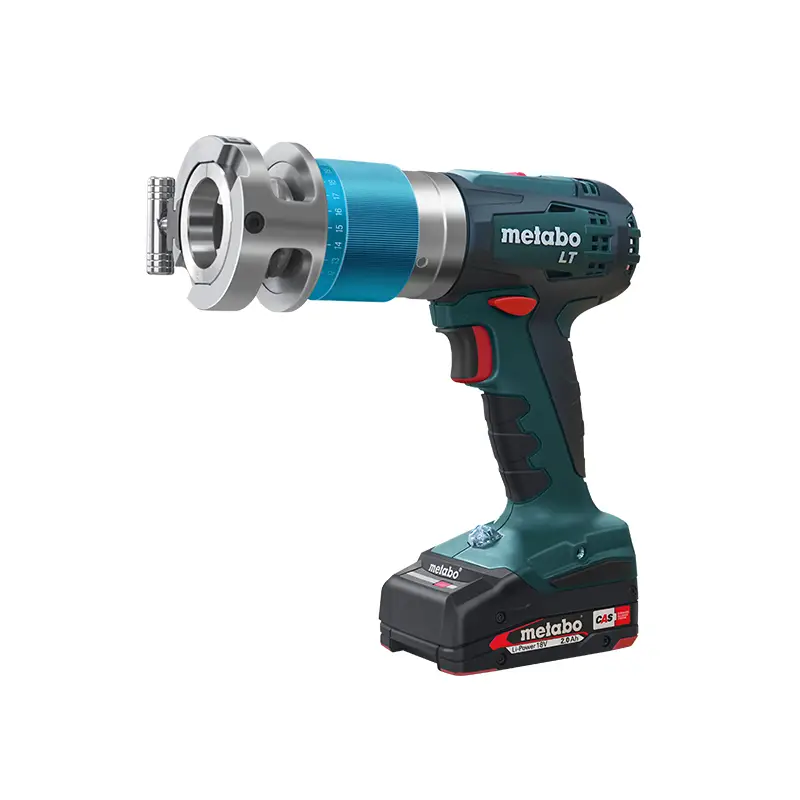
Three features carry the quality argument. The cutting chamber is enclosed, which keeps chips and noise away from the operator and matters on any site where OSHA or EU exposure limits apply. Feed depth adjusts in 0.01 mm increments, so material removal can be trimmed rather than guessed. And the drive is an industrial Metabo motor, chosen because the failure mode of a cheap motor on this duty is losing torque mid-face, which leaves a stepped end that looks faced and is not.
Once the ends are faced, tube-to-tube sheet welding becomes a geometry problem the head can solve. That is the point at which the tube sheet welding machine takes over, and why the two are usually specified together: an exchanger welded on badly faced ends will produce a defect rate that looks like a welding problem and is not.
A bevel is a code-driven shape, not a preference. ISO 9692-1 sets out the standard preparations, and ASME B16.25 defines the pipe end preparation used across B31 codes. In practice five profiles cover almost all work.
The tolerances around these shapes are where most preparation losses hide. A typical specification allows plus or minus 2.5 degrees on the bevel angle and a root face of 1.6 mm with plus or minus 0.8 mm. Land too thick and the arc cannot reach the root, so the joint closes with lack of penetration. Land too thin and the root drops through, so the welder chases it from the inside and the result is a lump that fails radiography. Both failures are created by the beveler, both are found by the welder, and neither is fixed by changing the weld program.
On wall above 20 mm the economics also shift. A 60 degree V on 25 mm wall consumes far more filler and arc time than a U preparation of the same depth, which is why thick-wall pipe shops tend to buy a machine that can produce a J or U rather than a plain beveler.
The same pipe can justify completely different machines depending on where the joint is made. The table below is the decision most buyers actually face.
| Working situation | Recommended equipment | Why |
|---|---|---|
| Shop cutting of long stock to length | Planetary cutter on a bench, Q3 or Q4 by range | Pipe stays still, ends stay square, no abrasive dust in the shop |
| Field tie-in on a line that cannot rotate | Portable planetary cutter, clamp-on | Only a rotating-tool design can work on an installed spool |
| Heat exchanger or boiler tube sheet | Tube facing machine plus tube sheet welding head | Thousands of short ends; facing cycle time sets the schedule |
| Thick-wall header or heavy pipe | Stationary beveler with U or J capability | Filler volume and arc time, not cutting speed, drive the cost |
| Sanitary, semiconductor or high-purity line | Cold cutting, no abrasive, enclosed chamber | Grit embedment and heat tint cannot be purged out |
| Plastic, PE, PP or PVC pipe | Planetary cutter with polymer blade set | Different chip formation; metal blades tear rather than cut |
Two of these deserve a second look because they are regularly bought wrong. The first is field work: buyers often purchase a stationary beveler for site use and discover that the pipe cannot be brought to the machine. The second is the high-purity case: an abrasive saw is cheaper by an order of magnitude and will pass a visual check, but the grit pressed into the cut face shows up later as porosity that only appears after the joint has been welded and radiographed.
Cutting parameters are not transferable between alloys, and the differences are large enough to affect tool life and end quality on the first shift.
Preparation is finished when it measures, not when it looks right. Five checks catch nearly every end that will later produce a defect.
Recording these five values on the first joint of a batch, and again after any tool change, is enough to separate preparation problems from welding problems when a defect does appear. Without that record, every failure gets investigated as a welding issue and the real cause stays in the tool.
Across pipe fabrication the two most common volumetric defect types found by radiography are lack of fusion and incomplete penetration, and both are geometry-sensitive at the root. A joint prepared with a thick land, a steep included angle or a sloped end face narrows the window in which the arc can establish a root without either missing the side wall or dropping through.
ASME B31.3 and the equivalent European codes handle this by controlling the preparation, not the welder: the joint detail is specified, the tolerance is specified, and the qualification coupon is made on a joint that complies. When a shop's defect rate is higher than its procedure should produce, the preparation route is the first thing worth auditing, because it is the one variable that is checked once at the start and then assumed for the rest of the batch.
The same logic runs through orbital work. An orbital head is a machine that repeats a program; if the joint it is presented with varies, the program repeats faithfully onto a varying condition. This is why the two landing pages for orbital welding machines and for tube sheet welding both start from end preparation rather than from the power source.
Cutting separates the pipe. Facing flattens and squares the end that the cut left behind, without changing the profile. Beveling forms the weld preparation itself, typically a V, U or compound shape. A cut end is not weld-ready, a faced end is weld-ready only for a square butt joint, and a beveled end is weld-ready for the profile it carries.
It can produce a square cut that is square enough to weld on thin wall, and it produces it without heat or abrasive contamination, which is why it is preferred on stainless and high-purity lines. A true bevel with a defined angle and land is a separate operation and normally needs a beveling head or a beveling machine.
The published envelope in this range is 1 to 5 mm on the Q3 frame at 6 to 76.2 mm OD, and 1 to 7 mm on the Q4 frame at 12.7 to 114.3 mm OD. Above that the cut quality depends more on frame rigidity and clamp stiffness than on motor power, which is why heavier wall moves to a different class of machine rather than to a bigger motor.
Yes, and for a specific reason. Tube sheet joints are short, thin-walled and repeated by the thousand, so the operation that matters is facing cycle time rather than cutting speed. A tube facing machine also removes the work-hardened rim left by the tube cutter, which is where lack-of-fusion defects usually start on stainless exchangers.
Measure four points around the circumference for angle, check the root face with a land gauge, check squareness with a square or indicator, and inspect the bore edge for burr. Record the values on the first joint of the batch. If a defect appears later, that record tells you immediately whether the tool or the arc is responsible.
Outside diameter, wall thickness, material and whether the joint is made in a shop or on site. With those four answers we can say whether the work belongs on a planetary cutter, a facing machine, a beveler, or a combination, and what the end face will measure when it comes off the tool.
Request a preparation review


