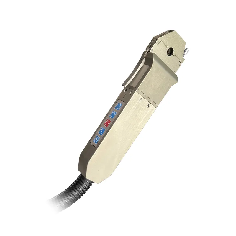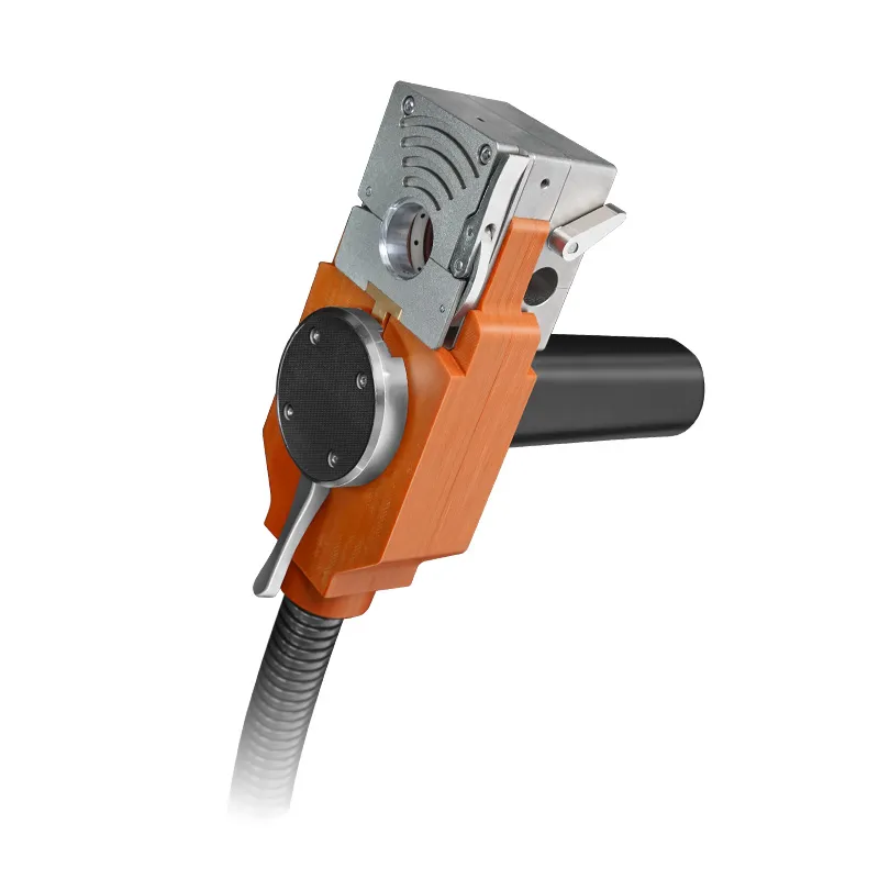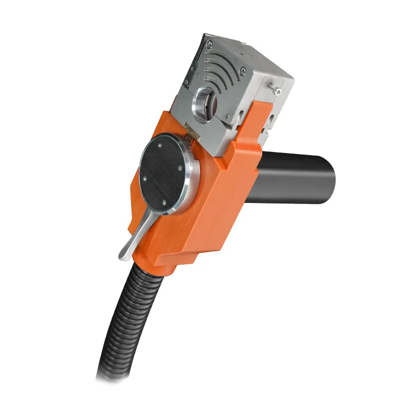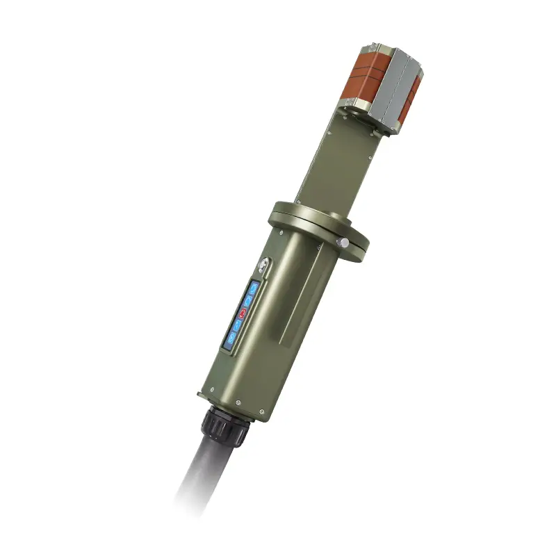

An orbital welding machine does not make a welder out of a non-welder. It removes four decisions from the operator's hands — rotation speed, arc length, current profile and gas coverage — and hands them to a controller that repeats them identically on every joint. Everything else about the machine follows from that one idea.
Hand TIG on a tube is a continuous correction loop. The welder watches the puddle, adjusts travel, shortens the arc when the joint wanders, feathers the current at the start, hesitates at the overlap. Four variables, adjusted by eye, dozens of times per joint.
Orbital TIG replaces each of those four with a parameter:
What the operator keeps is the part the machine cannot see: cleaning the joint, setting the tube projection, clamping the head on axis, choosing the program, and dressing the tungsten. Those four steps are where most bad welds originate, and no controller fixes them. If you are new to the process, start with our guide to orbital TIG welding before comparing machines on price.
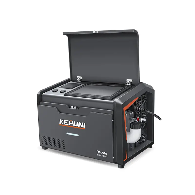
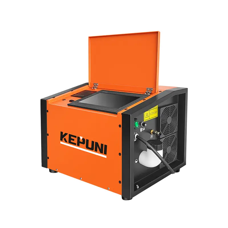
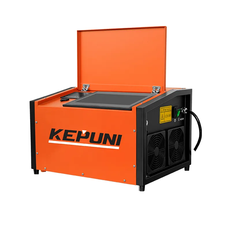
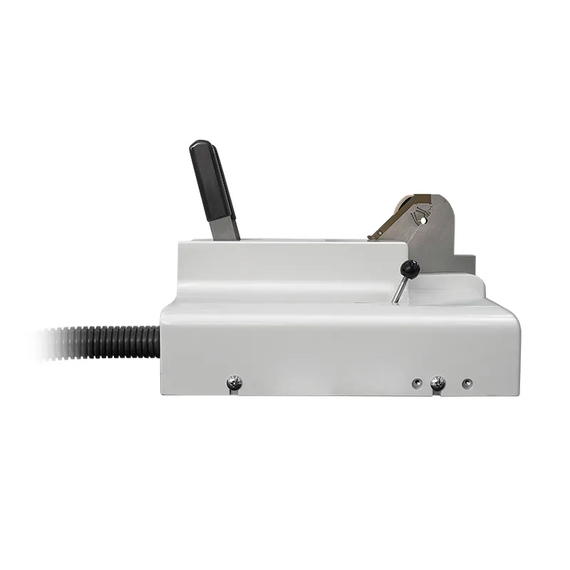
KEPUNI builds three power sources and three head families on the same platform. The figures below are the manufacturer's published specifications, not estimates.
| Model | Tube / pipe OD | Wall thickness | Why you would choose it |
|---|---|---|---|
| XD-20WSealed-head power source | 3.175–168 mm | 0.5–3 mm | The workhorse: expert database, 12 weld intervals, per-interval data logging, low-residue bead that needs minimal post-weld cleaning |
| XD-20PRO2023 upgrade of the 20W | 3.175–168 mm | 0.5–3 mm | 600 stored weld formulas, 2,000-record log, live argon flow display, water flow and temperature alarms, 10-language interface, automatic head recognition |
| XD-PD200Compact digital power source | 3.175–168 mm | 0.5–3 mm | Simulation mode to dry-run the head and program before striking an arc; full over-voltage, leak and tungsten-short protection set |
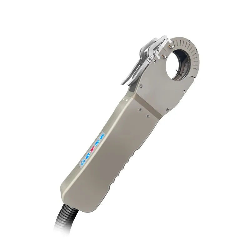
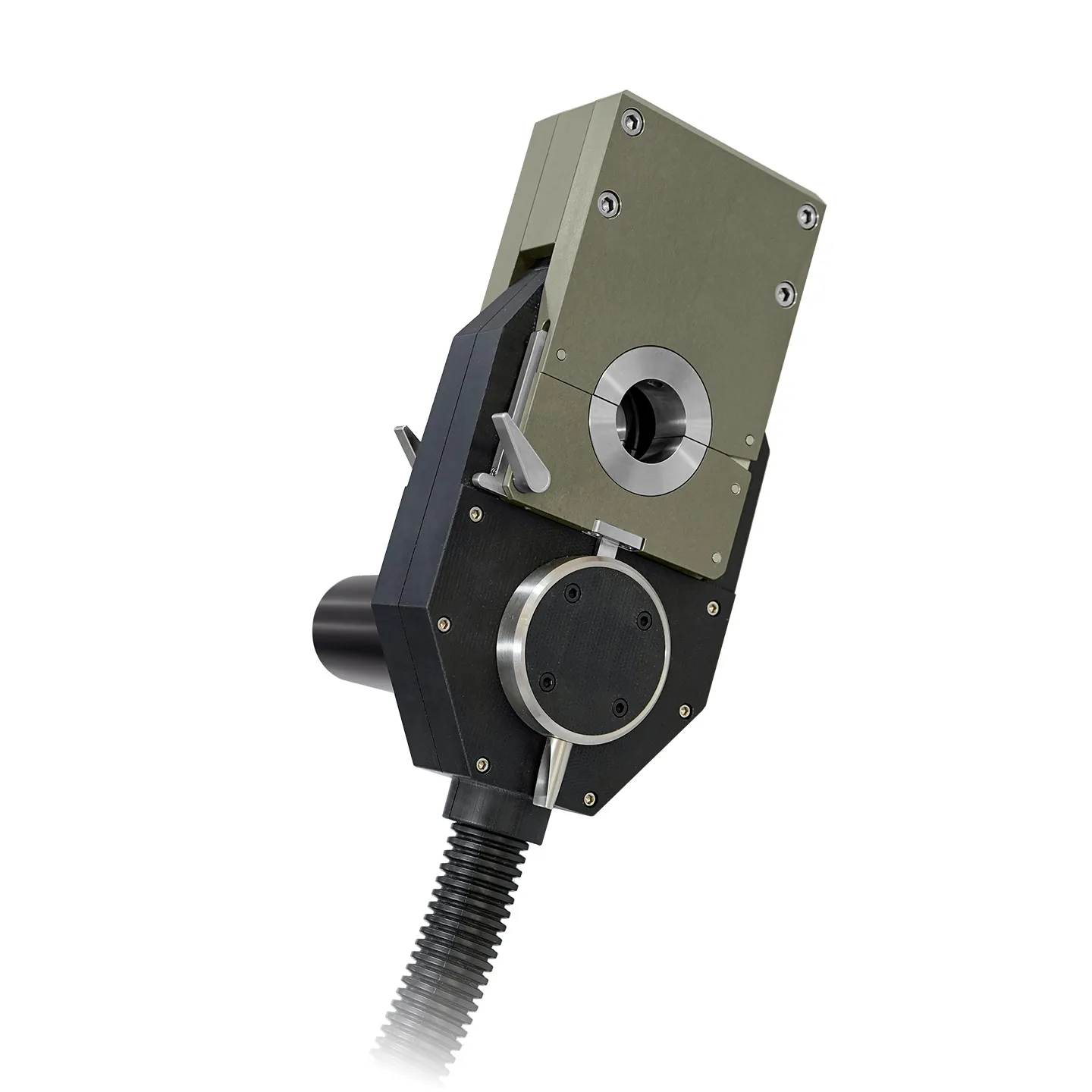
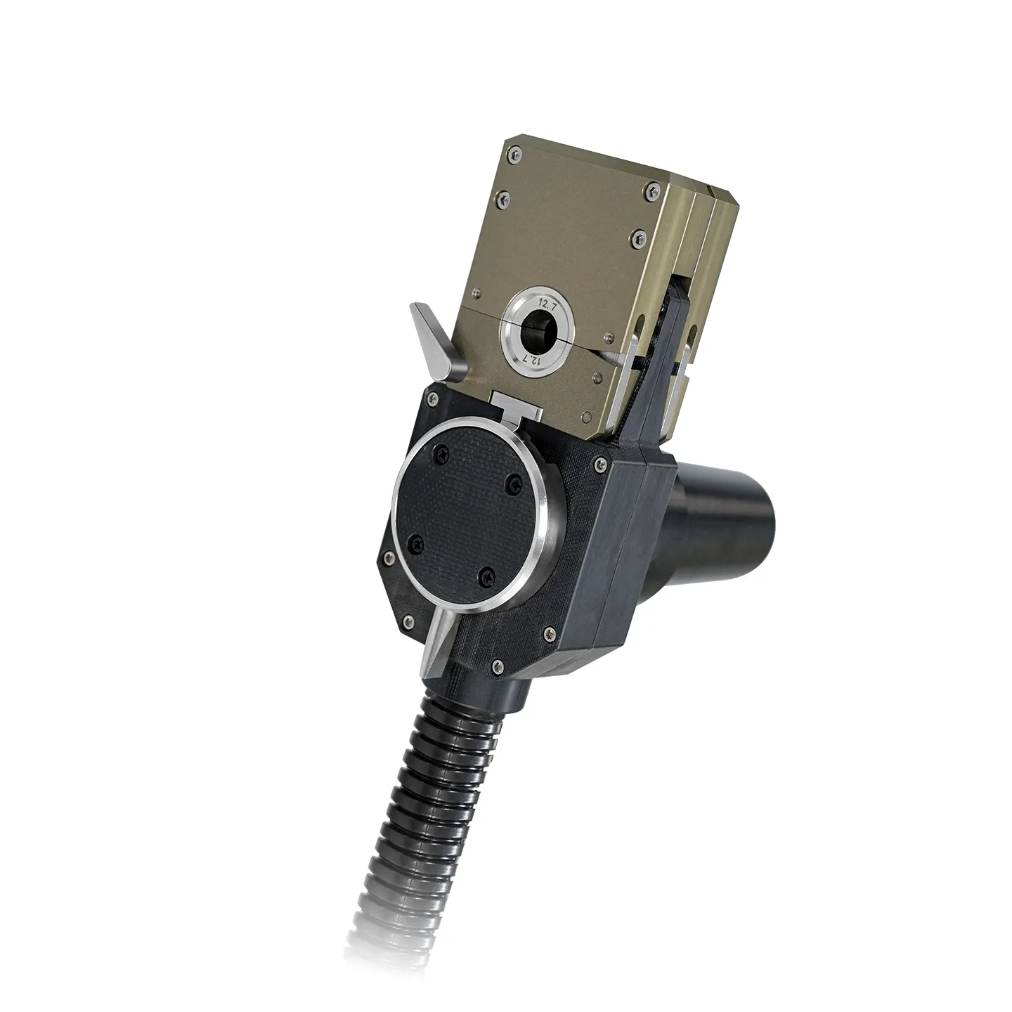
| Closed head systemSealed head, 40 / 80 / 120 / 170 bodies | 6.35–168 mm | 0.5–3 mm | Fully enclosed arc: blocks UV and IR, meets the enclosure requirements of OSHA and EN 169, suited to cleanroom and pharmaceutical work |
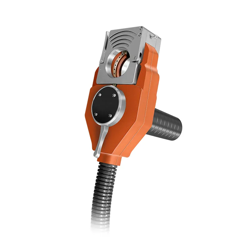
| Enclosed exchanger torchU-track and T-pullout bodies | 9.3–25 mm | 0.5–1.5 mm | Tube-to-tubesheet work in exchangers and boilers: water-cooled Z-series gearbox, pneumatic clamping, custom pipe spacing in two weeks |
| 5H split headMiniature split head | 3.18–15.88 mm | See drawing | Eccentric 5H body for gas lines and instrument tubing where a closed head cannot be slipped over the joint; quoted at 10-day delivery |
The wall-thickness column is the reason two machines with identical OD ranges are not interchangeable. A power source that will happily run 3 mm wall at 40 A will not hold a bead on 0.5 mm sanitary tube without a different programme, a smaller electrode and tighter heat input control.
The most common specification mistake we see is a buyer selecting a head by weld quality. All three head types produce code-quality welds; they differ in what they can physically reach.
A closed head is a ring. It slips over the tube end before fit-up and rotates a full 360° inside a sealed body. It gives the best arc protection because the enclosure is complete, and it is the fastest to run on repetitive work: clamp, index, start. Its limit is upstream — the tube must have a free end to pass the head over, and there must be clearance around the joint for the body to rotate.
A split head opens into two halves and clamps around the tube, so it can weld a joint in the middle of a bent line, a manifold, or a rack where no free end exists. The trade-off is that the arc is no longer fully enclosed and the head is more sensitive to how squarely it is seated. The 5H body covers 3.18–15.88 mm — semiconductor gas lines, instrument tubing, small sanitary runs.
Above roughly 168 mm the head stops being a ring and becomes a carriage on a track or a ring clamped to the pipe. The open range adds an integrated wire feeder, a water-cooled torch rated for continuous duty, and self-contained tooling. This is the configuration used for pipeline tie-ins, spool work and field joints, and it is the same controller and operator interface as the small-bore machines.
A weld program on the XD platform is divided into twelve intervals. Each interval is a slice of the rotation with its own settings, which is what allows one continuous 360° pass to behave differently at the start, the body and the close-out.
Because the intervals are stored with the program rather than dialled in by the operator, a repeat order made six months later runs the same numbers as the qualification weld. That is the practical difference between a welding position and a welding process.
The 20PRO exists because most orbital weld failures are detected after the fact — a penetrant test the next morning, a leak test after hydro. Its additions are aimed at catching the cause during the pass rather than after it.
| Defect | Usual cause | What the process does about it |
|---|---|---|
| Grey or coloured bead | Purge lost inside the tube, pre-flow too short, trailing shield too small | Timed pre-flow, sealed purge path, flow monitored at the head rather than at the regulator |
| Porosity | Cutting oil, moisture, marker pen or oxide in the joint | Defined cleaning and wipe-down before clamping; solvent and oxide are not parameter problems |
| Lack of fusion at the start | Cold weldment, step-change current, no upslope | Programmed upslope in the first interval |
| Crater or crack at close-out | Arc stops without overlap | 15–20° overlap past the start point plus downslope |
| Uneven penetration | Tube-end run-out, poor fit-up, arc length drifting | Arc voltage control, mechanical gap setting, projection held to the drawing |
| Arc wander, tungsten contamination | Blunt or chipped electrode, wrong grind, contact with the puddle | Electrode preparation standard and one-click change-out; a chipped tip changes arc shape unpredictably |
Six symptoms, and almost all of them originate before the arc strikes. Our guide to orbital welder maintenance sets out the daily and per-batch checks that keep the purge path, the electrode and the clamping consistent.
The standard database covers 304 and 316L stainless and carbon steel, which is what most sanitary, instrument and exchanger tubing is made of. Nickel alloys are covered on the 20PRO formula set. Reactive metals — titanium in particular — are a different conversation: they need full-bore purge, an oversized trailing shield and a heat-input window narrow enough that we weld a sample coupon before the machine ships.
Duplex and super duplex are sensitive to heat input and ferrite balance rather than to peak current, which means the rotation speed does more of the work than the amps. Copper alloys conduct heat away so fast that preheat and a shorter arc become part of the procedure. In all three cases the machine is the same; the programme and the gas plan are not.
Pharmaceutical and biotech skids on 3.175 mm to 25 mm sanitary stainless, where a low-residue bead cuts cleaning validation work downstream — the pharmaceutical and food processing applications are covered separately. Semiconductor and life-science gas lines on 3.18–15.88 mm tubing, welded with the 5H split body. Heat exchangers, condensers and boilers on the enclosed exchanger torch, at 9.3–25 mm and 0.5–1.5 mm wall. Oil and gas spool and tie-in work on the open track and wire-feed systems. Food, dairy, HVAC and refrigeration on thin-wall stainless where oxidation, not penetration, is the usual reject reason.
If the joint is on a boiler tube sheet rather than a pipe end, the head and the programme both change — see the tube-to-tubesheet range. If the work is stainless tubing in a hygienic circuit, our heat exchanger application notes cover the surface and purge requirements that apply.
| Hand TIG | Orbital TIG | |
|---|---|---|
| Consistency | Depends on the welder and the hour of the shift | Identical programme for every joint in the batch |
| Speed | Skilled operator, frequent repositioning, stop-start beads | Continuous 360° rotation, no repositioning mid-pass |
| Skill required | Years on thin-wall stainless | Fixture and programme selection; KEPUNI measures a 70% reduction in training time on the closed-head system |
| Rework rate | Rises sharply on small bore, thin wall and confined access | Set by programme validation rather than operator judgement |
| Traceability | Paper record at best | Stored parameters and per-weld log, exportable over USB |
| Best use | Repair, odd geometry, single joints, tight budgets | Production runs, repeated orders, code-critical and hygienic work |
Nine answers let us size the system without a second round of questions:
Send those and you get a head recommendation, a starting programme based on comparable jobs, and a price — usually the same working day.
3.175 mm OD on the XD-20 platform, and 3.18 mm on the 5H split head. Below that the arc, the purge path and the tungsten all start competing for the same space, and the joint is normally made by laser or by micro-TIG rather than by a rotating head.
If the tube has a free end and there is clearance to rotate a ring around the joint, use a closed head — the arc is fully enclosed and the weld is easier to repeat. If the joint sits mid-line in a manifold or a rack, or the tube is already bent, use a split head and accept the more careful seating it requires.
The controller is common, but the head is not. The XD-20 platform covers 3.175–168 mm; beyond that the joint moves to a track or ring carriage with a wire feeder and a water-cooled torch. Shops that do both typically keep one controller and two tooling sets.
Almost always gas, not amps. Either the pre-flow is too short, the purge is escaping from the far end of the tube, or the trailing shield is undersized for the joint. Check flow at the torch, seal the far end, and confirm the regulator is not the only place where flow is being measured.
Arc time on a 25 mm stainless joint is measured in tens of seconds. Real throughput is set by indexing — unclamping, moving to the next joint, reseating the head — which is why fixture design and head weight matter as much as weld speed on production bundles.
Same OD and wall range, same 12-interval programme structure. The 20PRO adds live argon flow with alarms, water flow and temperature monitoring, 600 stored formulas, a 2,000-record log, a 10-language interface, automatic head recognition and one-click tungsten change.
Yes for the open-track and wire-feed configurations, which are built for spool and tie-in work. The constraint is services rather than the machine: on-site welding needs stable argon, clean water for the torch circuit and a supply that will carry the duty cycle.
We supply the parameter starting point, the coupon support and the documentation package. The qualification itself is issued by your welding engineer or an accredited body, because it has to cover your material, your joint design and the code you are working to.
Tube OD, wall thickness, material and whether the joint can be encircled — that is enough for us to recommend a head, propose a starting programme and quote. If you are moving from hand TIG, we will also tell you what the first week of changeover looks like.
Request an orbital welding review